
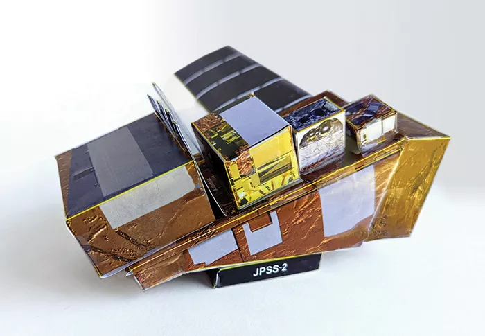
Put your engineering skills to the test by assembling a paper model of JPSS-2 using simple household supplies like tape and glue.
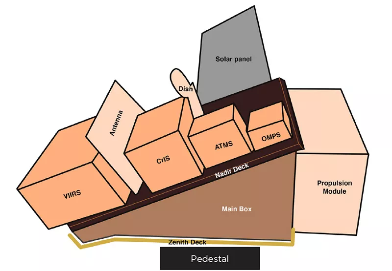
This activity will help you learn more about the JPSS-2 satellite as you fold and attach all of its components. The step-by-step instructions will help you build the Advanced Technology Microwave Sounder (ATMS), the Cross-Track Infrared Sounder (CrIS), the Visible Infrared Imaging Radiometer Suite (VIIRS), the Ozone Mapping and Profiler Suite (OMPS), the solar panel, the main bus and a stand for displaying your creation.
NOTE: The components of the paper model in this PDF are not perforated. They need to be cut out with scissors into separate pieces for folding. It is recommended that you print out the template pages on heavy stock paper, like card stock.
Materials Needed
- Tape or craft glue
- (Optional) a metal ruler or straight edge for creating crisp folds.
Guidelines
Yellow lines indicate fold lines, where the model should be folded. White areas are tabs. Pieces are labeled with component’s names.
Tips
Pieces are directional. Make sure the pieces are facing the correct direction—match up the blue triangles—before applying glue or tape. Don’t use glue sticks. While using glue will lend for a polished model with cleaner seams, double-sided tape can be efficient and make for a stronger model.
Overview
-
Gather your materials.
-
Look over the model and general placement of components.
-
Carefully pop-out all of the pieces. (If you are printing the templates from the PDF, it is recommended you print out the template pages on heavy stock paper, like card stock. Then cut the along the black outline into separate pieces.)
-
Fold along all of the yellow lines before assembling.
-
Assemble each component with glue or tape. See instructions for details.
-
As you attach the components to each other, refer to the blue triangles for positional alignment.
-
Build the pedestal for your JPSS-2 model to rest upon.
The Components
|
Instruments:
|
Instructions
1. Pop out the pieces.
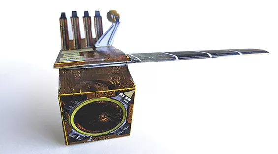
Begin folding and assembling the Propulsion Module and all of the instruments using tape to create the shapes. Make folds along all of the yellow lines. It can be helpful to crease all of the folds before attempting to form the shape. If there are double lines, fold along both of them.
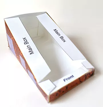
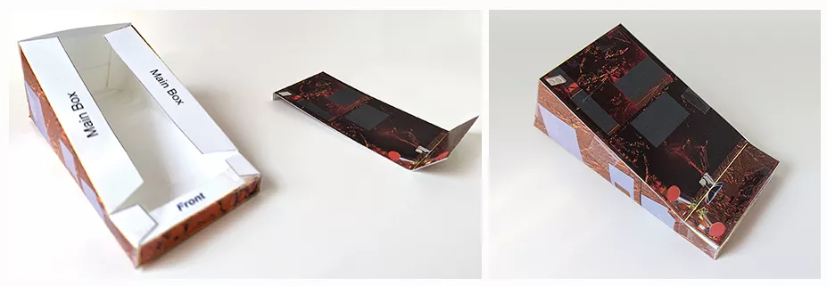
2. Assemble the Main Box.
3. Attach the Zenith Deck to the bottom of the Main Box.
Wrap the Zenith Deck piece along the bottom contour of the Main Body. Tuck the Zenith Deck Back tab under the Propulsion panel. Tape both ends to secure.
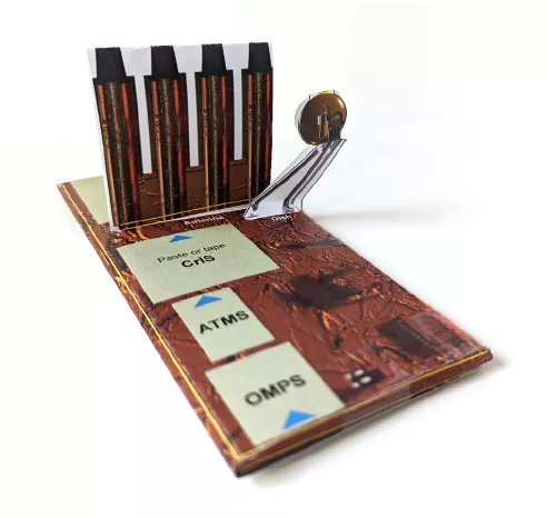
4. Insert the Dish and Antenna into the pre-cut slits on the Nadir Deck.
Flip the Nadir Deck over. Secure the Antenna and Dish by taping the tabs flat onto the Nadir Deck.
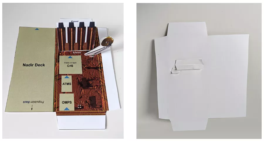
5. Finish assembling the Nadir Deck.
Fold in the tabs, and finally seal the large tan flap, labeled, “Nadir Deck” to complete the component.The Nadir Deck should be a thin box when it is folded correctly.
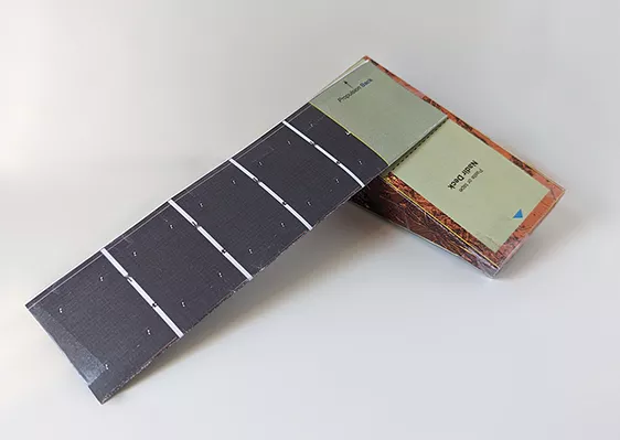
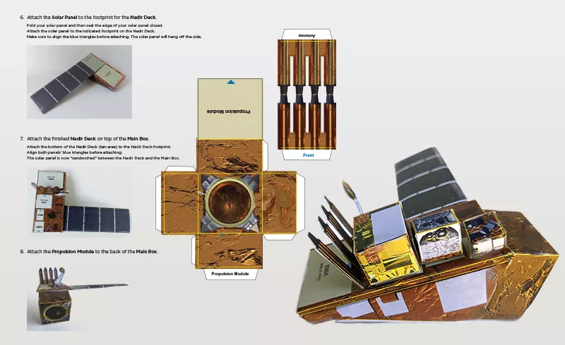
6. Attach the Solar Panel to the footprint for the Nadir Deck.
Fold your solar panel and then seal the edge of your solar panel closed. Attach the solar panel to the indicated footprint on the Nadir Deck. Make sure to align the blue triangles before attaching. The solar panel will hang off the side.
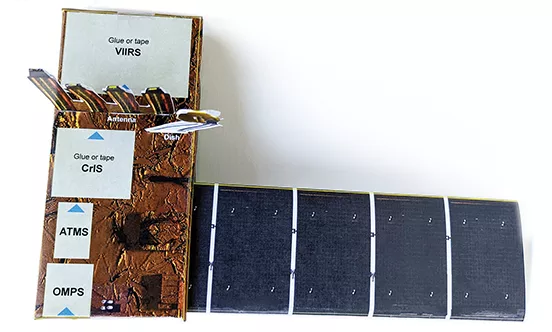
7. Attach the finished Nadir Deck on top of the Main Box.
Attach the bottom of the Nadir Deck (tan area) to the Nadir Deck footprint. Align both panels’ blue triangles before attaching. The solar panel is now “sandwiched” between the Nadir Deck and the Main Box.
8. Attach the Propulsion Module to the back of the Main Box.
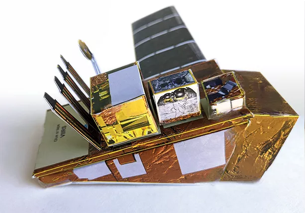
9. Attach the ATMS, CrIS, and OMPS to the labeled footprints indicated on the Nadir Deck.
Don’t forget to align the blue triangles before attaching.
10. Attach VIIRS so that a portion of the cube is attached to the Nadir Deck where indicated and the other part of it is floating.
11. Assemble the Pedestal and set your completed spacecraft on the stand.